
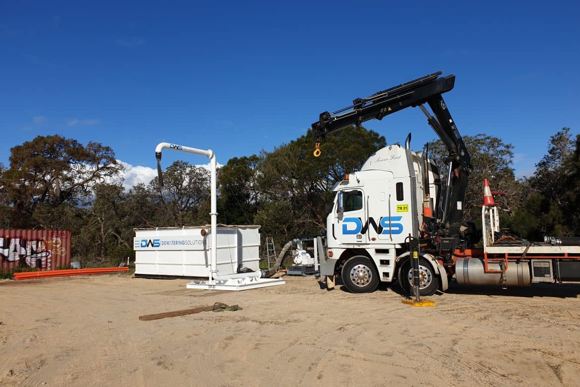
Groundwater does not wait for a revised programme or a delayed mobilisation. Once an excavation reaches a permeable water-bearing layer, uncontrolled inflow can soften formation levels, destabilise batters, restrict plant access and put critical works behind schedule. A well-prepared deep well dewatering method statement sets out how these risks will be controlled before drilling begins and throughout the excavation.
For deep excavations in sands, gravels, fractured rock or other permeable ground, a deep well system can provide the drawdown that wellpoints and sump pumping cannot reliably achieve. The method statement is not a generic paperwork exercise. It should translate the site investigation, design intent and environmental obligations into a clear field plan that crews, supervisors and the principal contractor can apply under changing site conditions.
What a deep well system is designed to achieve
Deep well dewatering uses screened wells installed below the proposed excavation level. Submersible pumps remove groundwater from each well through a header system or individual discharge lines, lowering the groundwater table around and beneath the work area.
The primary objective is usually to achieve and maintain a specified drawdown below formation level. That protects excavation stability, reduces seepage pressures and gives construction crews a workable, safer platform. On some projects, the system also needs to limit groundwater pressures beneath a base slab, manage inflow to shafts or pits, or support staged excavation around existing services and structures.
The required drawdown is site-specific. It depends on permeability, aquifer thickness, recharge, excavation geometry, nearby water bodies, tidal influence, rainfall, neighbouring foundations and the duration of works. A method statement must acknowledge those variables rather than promise a fixed outcome without verification.
What the method statement must establish before mobilisation
A credible deep well dewatering method statement starts with the available ground and water data. Bore logs, test pits, groundwater monitoring records, pumping tests, laboratory results and design drawings should be reviewed together. The goal is to identify where water is coming from, how readily it will move through the ground and what may be affected if levels are lowered.
The document should clearly define the scope: the excavation area, target drawdown, nominated well locations, expected flow rates, discharge point, operating period and responsibilities. It should also identify interfaces with piling, shoring, bulk earthworks, crane access, underground services and concrete works. Dewatering is often treated as a separate trade, but it directly affects nearly every activity below ground.
Before mobilisation, the project team should confirm approvals and site constraints. These may include discharge requirements, water quality limits, sediment controls, groundwater licensing considerations, heritage conditions, contamination risks and restrictions on discharge to stormwater, sewer or nearby land. Requirements differ by location and project, so assumptions need to be tested early.
Establish the design basis
The design basis should state the information used to size and locate the system. This includes anticipated soil and rock conditions, aquifer characteristics, target water levels, estimated pumping rates and any allowance for rainfall or recharge.
Where information is limited, the method statement should explain how the system will be validated in the field. A staged installation, trial well or pumping test may be appropriate before committing to full production. This approach manages uncertainty without delaying the whole project until every variable is known.
Installation sequence and controls
The installation section should set out a practical sequence that matches the site programme. It needs to describe how drilling will be undertaken, how wells will be constructed and developed, and when pumps will be commissioned. It should also address access, exclusion zones, lifting arrangements and spoil management.
A typical sequence includes:
- survey and service identification before drilling;
- establishment of drilling pads, bunding and sediment controls;
- drilling to the specified depth using a suitable method for the ground conditions;
- installation of screen, riser pipe, filter pack and well seal;
- well development to remove fines and improve hydraulic connection;
- installation of submersible pumps, electrical controls and discharge pipework; and
- controlled commissioning, testing and monitoring before excavation proceeds.
The exact sequence changes with geology. In loose sands, filter pack selection and development are critical to prevent sand pumping and loss of capacity. In fractured rock, well yield can vary significantly between locations. In contaminated ground, drilling fluids, cuttings and extracted water may require additional containment and handling controls.
The statement should specify how the wells will be protected from damage by plant and traffic. Wellheads need to remain accessible for inspection while being clearly marked, barricaded where necessary and kept out of active haul routes. Pipework must be restrained, supported and routed so it does not create trip hazards, block access or fail under plant movements.
Managing pumped water responsibly
Water management is as important as water removal. The method statement must identify the proposed discharge route and the treatment steps needed to meet project and regulatory requirements. Depending on water quality, this may involve settlement tanks, sediment basins, bag filters, cartridge filtration, oil-water separation, pH correction or specialist treatment for dissolved contaminants.
Discharge controls should be based on testing, not appearance alone. Clear water can still contain dissolved salts, metals, hydrocarbons or other contaminants that make direct discharge unsuitable. Baseline sampling before pumping and scheduled monitoring during operation provide the evidence needed to adjust treatment and demonstrate compliance.
The plan should also cover wet-weather contingencies. Heavy rain can increase runoff, overload treatment equipment and flood low points even when groundwater drawdown is performing as designed. Separate surface-water controls, diversion measures and standby pumping capacity help prevent one water source from compromising control of the other.
Safety and environmental risk controls
Deep well systems introduce drilling, electrical, lifting, pressurised pipework and water-management hazards to an already busy construction site. The method statement should connect directly to the project risk assessment and safe work procedures, with controls that are specific to the work area.
Key controls generally include verified underground service locations, competent drill crews, exclusion zones around rotating equipment, tested lifting gear, electrical protection and lock-out procedures for pumps, and secure management of hoses and discharge lines. Excavations must be monitored for instability, erosion, piping or unexpected inflows, particularly during commissioning and after significant rainfall.
Environmental controls need the same discipline. Fuel and chemical storage should be bunded, drilling spoil contained, turbidity controlled and any water-quality exceedance escalated promptly. If drawdown has the potential to affect nearby structures, bores, wetlands or contaminated groundwater, the statement should set trigger levels and response actions before pumping starts.
Monitoring proves the system is working
A deep well system should not be judged by whether pumps are running. It should be judged by measured groundwater levels, discharge performance, water quality and excavation conditions.
The method statement should nominate monitoring locations, frequency, instruments, recording requirements and reporting lines. Observation bores inside and outside the drawdown area provide a clearer picture than pump flow alone. Regular readings help identify a blocked screen, failing pump, unexpected recharge pathway or drawdown extending beyond the intended zone.
Trigger action response plans are particularly valuable on high-risk sites. For example, if groundwater remains above the required level, excavation may need to pause while additional wells, pump adjustments or further investigation are completed. If drawdown occurs too rapidly near sensitive assets, pumping rates may need to be reduced or modified. Defined triggers turn field data into timely decisions.
Maintenance, standby capacity and handover
Dewatering is a 24-hour control measure on many projects. A system that performs during commissioning but fails overnight can quickly undo days of progress. The method statement should set out inspection intervals, pump maintenance requirements, refuelling or power arrangements, alarm response and contact escalation.
Standby pumps, spare hoses, electrical components and emergency power may be justified where inflow is high or excavation stability depends on continuous drawdown. The appropriate level of redundancy depends on the consequences of failure, not simply the number of wells installed.
When dewatering is no longer required, shutdown should be planned rather than abrupt. Groundwater recovery can affect excavation works, slabs, structures and adjacent ground. The statement should describe how pumping will be reduced, how water levels will be monitored during recovery, and how wells, pipework and treatment equipment will be removed or decommissioned safely.
At Dewatering Solutions, the focus is on making the method statement usable in the field: a document that aligns design, site operations, safety and environmental controls. The strongest plans give project teams a clear path to act early when conditions change, protecting the excavation and the programme when it matters most.