
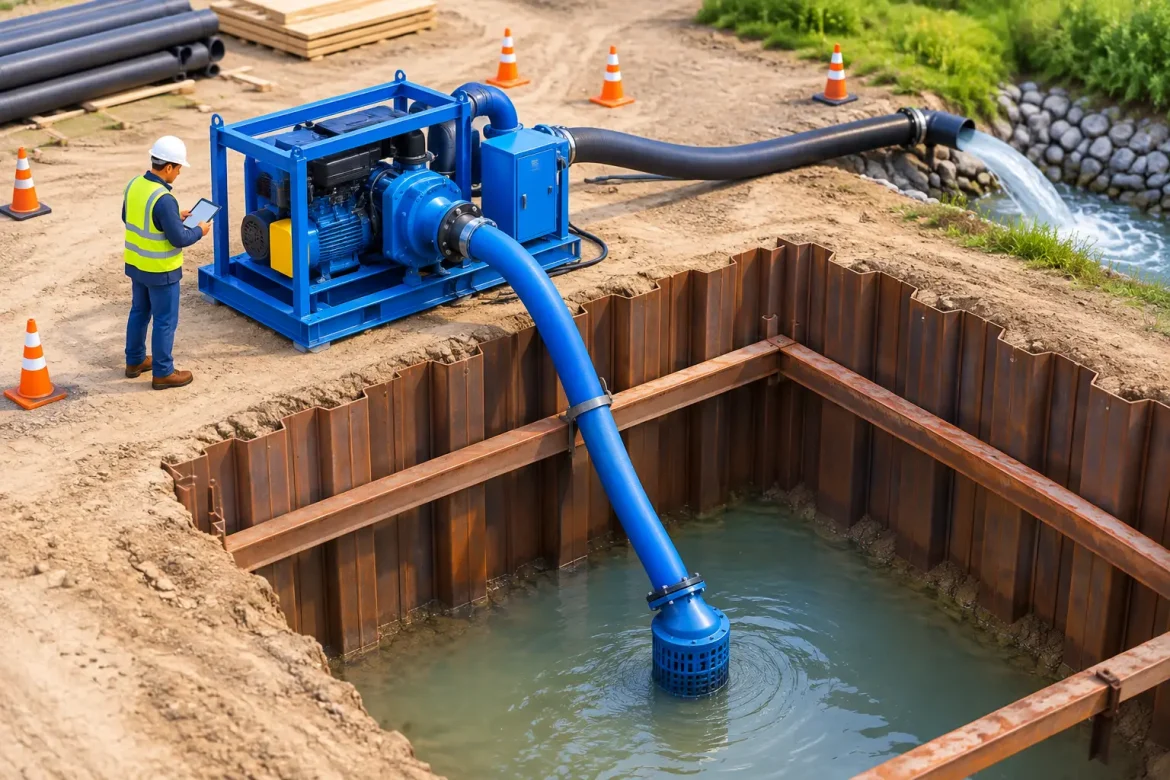
A pump that moves enough water on a clean test run can still fail the job once rainfall, sediment, changing excavation levels and discharge constraints come into play. To choose a dewatering pump setup properly, project teams need to assess the whole water-control system, not simply nominate a pump size. The right arrangement protects excavation stability, keeps crews working safely and prevents groundwater from becoming a programme and cost issue.
For construction, civil and mining works, pump selection starts with what is happening below ground and where the water must go after extraction. Local ground conditions matter. A shallow sandy excavation, a deep basement cut in mixed soils and a mine site sump receiving dirty runoff each require a different approach.
Start with the source of water
Before calculating flow rates, establish whether the water is groundwater, surface runoff, process water or a combination of all three. Each source behaves differently and changes the setup required.
Groundwater entering through permeable sand or gravel may require wellpoints or deep wells to lower the water table before excavation progresses. Pumping from the bottom of an excavation in these conditions may remove visible water without reducing pore-water pressure in the surrounding ground. That can leave batter faces, trench walls or formation levels unstable.
By contrast, a contained excavation receiving stormwater or minor seepage may be suited to sump and open pumping. Water is directed through graded drains to a collection point, then removed with a suitable pump. This is often effective and economical where inflows are manageable and the ground remains stable, but it is not a substitute for groundwater drawdown where the soil profile demands a deeper intervention.
A site investigation, bore logs, trial pits, historical groundwater information and observations from nearby works provide the starting point. They should be read alongside the construction sequence. The critical question is not only how much water is present now, but how inflow will change as excavation deepens, rainfall occurs or adjacent drainage paths are interrupted.
Choose a dewatering pump setup around duty point
Pump capacity is commonly described by flow rate, but flow alone is not enough. Every pump has a duty point: the flow it can produce at a particular total dynamic head. If the head is underestimated, a pump that appears generously sized may deliver far less water than expected.
Total dynamic head includes the vertical lift from water level to discharge point, friction losses through hoses and pipelines, losses through bends, valves and fittings, and any pressure required at the final discharge arrangement. A long discharge line across site, a rising main to a treatment unit or a pipeline routed over an embankment can materially alter the pump duty.
The suction side deserves equal attention. Surface-mounted pumps have practical limits on suction lift, and performance falls when the pump is too far above the water level or suction lines are poorly sealed. Long suction hoses, air leaks, blocked strainers and excessive lift can cause loss of prime, cavitation and inconsistent output. Where water levels will fall significantly, a submersible pump, wellpoint system or staged pumping arrangement may be more reliable.
Allow for a sensible operational margin, but avoid excessive oversizing. An oversized pump can create unnecessary fuel use, wear, noise, turbulence and sediment mobilisation. It may also cycle poorly at low inflows. The objective is stable performance across the expected range of conditions, with standby capacity where the consequences of failure are high.
Match the pump to water quality and solids
Water quality is often the point where an apparently straightforward setup becomes a maintenance problem. Clear groundwater, silty seepage, abrasive sand, clay slurry and water carrying construction debris do not belong in the same pump category.
For relatively clean water, a standard dewatering pump may be appropriate. Where fine sediment is expected, the setup may need settlement, filtration or a treatment process before discharge. For abrasive slurry or water containing larger solids, pump materials, impeller design and solids-handling capability become critical. A pump selected only for nominal flow can suffer blocked passages, rapid wear or repeated breakdowns when faced with the actual site water.
Sump design has a direct effect on pump reliability. A poorly formed sump allows sediment to accumulate around the intake and can pull air into the system as water levels fluctuate. Providing adequate volume, controlled inflow and a stable pump position reduces short cycling and makes maintenance safer. In some cases, using staged sumps or separate settlement areas is preferable to concentrating all water and sediment in one location.
Design the discharge route before pumping begins
Removing water from an excavation is only half the task. The discharge route must have capacity, be physically secure and meet project and environmental requirements. Sending silty water to a drain, waterway or neighbouring property creates a risk that can quickly outweigh the benefit of fast pumping.
Confirm the approved discharge location, allowable water-quality limits, required monitoring and whether treatment is necessary. Depending on site conditions, this may involve sediment basins, settlement tanks, filtration, pH adjustment, oil-water separation or controlled reuse on site. The treatment system must be sized for peak flows as well as normal operation. A treatment unit that is undersized can become the bottleneck even when the pumps are performing as specified.
Discharge pipelines should be routed and restrained to prevent trips, vehicle damage, uncontrolled movement and leaks. Consider crossings, traffic management, public interfaces and potential erosion at the outlet. In sensitive areas, secondary containment and regular inspection may be warranted. A clean discharge record is not simply a compliance outcome – it protects the project from avoidable delays and remediation costs.
Build redundancy into critical operations
The required level of backup depends on the consequence of water returning to the work area. A shallow excavation with low seepage may only need a readily available replacement pump. A deep excavation, rail corridor, major foundation pour or mining operation can require duty and standby pumps, backup power, automated level controls and remote alarms.
Redundancy should extend beyond the pump itself. Spare hoses, fittings, fuel arrangements, power leads, strainers and trained personnel are often what determine whether a fault is resolved quickly. If the system relies on generators, fuel management and generator capacity need to be assessed against starting loads and continuous demand. For electrically powered systems, confirm that supply capacity, protection and cable routing are suitable for wet-site conditions.
Automation can improve response times, particularly where inflow fluctuates outside normal working hours. Float switches, level sensors and telemetry are useful, but they do not remove the need for routine inspections. Sensors can foul, floats can snag and alarms need a clear escalation process with someone accountable for responding.
Plan installation around the construction sequence
A technically sound pump arrangement can still disrupt the project if it is installed without considering access and programme interfaces. Pumps, treatment equipment, pipelines and sumps need locations that allow safe refuelling, inspection and maintenance without obstructing excavation plant, crane paths, haul routes or concrete works.
Installation should also account for progressive excavation. A pump located at the original formation level may become inaccessible as the cut deepens. Likewise, wellpoint headers and risers need protection from plant damage, while discharge lines must be adjusted as work fronts move. Planning these changes early is usually less expensive than reactive relocations during a critical stage of works.
Noise, emissions and fuel storage may influence equipment choice, particularly near occupied buildings or environmentally sensitive areas. Diesel-driven pumps offer flexibility where power is unavailable, while electric submersibles can reduce local noise and eliminate on-site fuel handling where a reliable power supply exists. Neither is automatically better. The practical choice depends on access, duty requirements, energy availability, operating duration and site controls.
Use field monitoring to keep the setup effective
Dewatering is not set-and-forget work. Water levels, pump run hours, discharge quality, flow performance and excavation conditions should be checked against the expected behaviour of the system. A gradual fall in output may indicate a blocked strainer, worn impeller, damaged hose or changing groundwater conditions. Turbid discharge can signal a failed treatment process or excessive disturbance at the intake.
For groundwater drawdown, monitoring points can confirm whether water levels are being lowered sufficiently beyond the excavation itself. This evidence helps the project team make informed decisions on excavation progress, support requirements and system adjustments. It also provides traceability when conditions change or approvals require reporting.
Dewatering Solutions approaches pump selection as a site-performance decision: assess the ground, define the duty, control the discharge and maintain the system through changing conditions. The most effective setup is the one that keeps water out of the critical work zone without introducing new safety, environmental or programme risks.
Before committing equipment to site, test the proposed arrangement against the worst credible inflow, the actual discharge path and the next stage of excavation. That disciplined check can prevent a small pumping decision from becoming a major project interruption.