
A tunnel inflow control example is most useful when it reflects the decisions made at the face, not just the final pumping arrangement. Consider a civil tunnel drive approaching a fractured zone beneath a shallow water-bearing formation. Probe holes indicate rising pressures ahead of the face, while initial seepage through the crown and sidewalls increases during each advance. If that water is not controlled before excavation continues, the project can face loss of ground, reduced face stability, unsafe access, treatment delays and damage to the programme.
The right response is rarely to add larger pumps and keep driving. Effective inflow control starts with understanding where the water is coming from, how it is moving through the ground and what consequences continued drawdown may create beyond the tunnel alignment.
Tunnel inflow control example: fractured ground ahead of the face
In this example, the tunnel is being excavated through competent material before intersecting a weathered fault zone. The fault is connected to a permeable sand and gravel layer that carries groundwater under pressure. Pre-construction investigations identified variable conditions, but the exact width and transmissivity of the fault were uncertain.
At approximately 20 metres from the anticipated zone, the construction team begins systematic probe drilling from the face. Several holes return water under pressure, with flows increasing in holes angled towards the crown. The team pauses normal advance rather than exposing more ground. This is a controlled intervention, not lost production. Advancing into an uncharacterised inflow can create a far longer and more expensive recovery operation.
The immediate objective is to reduce inflow at the source, maintain stability around the excavation and manage the water that still reaches the tunnel. A workable control plan may combine pre-excavation grouting, staged excavation, drainage holes, localised support and a properly sized pumping and treatment system.
Step 1: confirm the source and risk
Probe drilling provides the first warning, but it does not answer every question. The site team records flow rates, pressure, water quality, drilling returns and the location of each wet hole. Piezometers, where practical, help establish whether pressures are reducing after intervention or simply shifting elsewhere.
The key distinction is between nuisance seepage and an active groundwater pathway. A wet face may be manageable with routine drainage. A pressurised fracture network or connection to a permeable aquifer demands a more deliberate design. The latter can transport fines into the excavation, loosen blocks around the crown or cause settlement above the tunnel if groundwater levels are lowered too aggressively.
Water quality also matters. Turbid inflow can indicate ground movement or erosion. Saline water, acidic conditions, hydrocarbons or elevated metals may change treatment, discharge and materials selection requirements. Water should not be assumed suitable for release simply because it is groundwater.
Step 2: reduce water before excavation reaches it
In this scenario, grouting is carried out through a fan of holes ahead of the face. The grout programme is staged, starting with lower pressures and carefully monitored volumes to avoid unintended ground heave or migration into unsuitable areas. The purpose is to fill or restrict the major flow paths in the fractured zone, rather than attempting to create an unrealistic completely watertight barrier.
Verification holes are drilled after the initial grout phase. If water pressure and inflow reduce to agreed limits, the tunnel can advance in short controlled rounds. If verification still identifies significant pathways, targeted secondary grouting is completed before excavation resumes.
This approach has a trade-off. Grouting takes time, consumes materials and needs close quality control. But it can be far more cost-effective than allowing a high-volume inflow to dictate the excavation sequence, overload treatment equipment or destabilise the ground. It also reduces the volume of water requiring ongoing pumping and disposal.
Where geology allows, drainage holes may be used alongside grouting to relieve local pressure in a controlled direction. These holes must be designed carefully. Draining a pressurised formation towards the face without adequate collection capacity can make conditions worse, not better.
Managing residual water inside the tunnel
No inflow-control system should rely on a single measure. Even after successful grouting, residual seepage and intermittent flows are expected. The tunnel invert is graded to collection points, with lined drains or temporary channels directing water away from work areas. Sumps are positioned so they do not undermine the formation, obstruct plant movements or become a trip and access hazard.
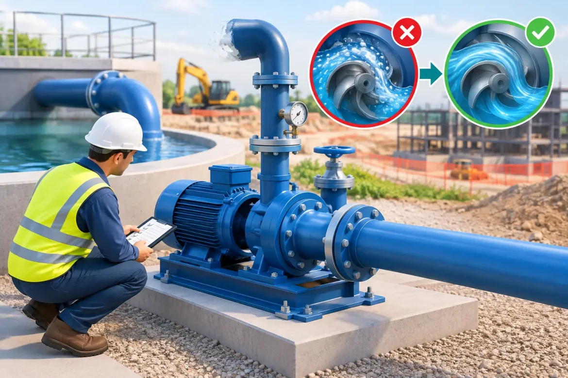
Pumps are selected for actual duty conditions, including head, solids handling, standby capacity and the likelihood of changing flows. A pumping arrangement that performs well during steady seepage may fail when a drilling operation opens a short-lived high-flow pathway. Duty and standby pumps, protected electrical supplies, level alarms and regular inspection are basic controls where loss of pumping could affect personnel or the excavation.
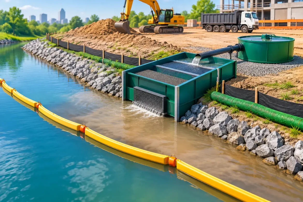
Collected water may require settlement, filtration, pH correction or oil-water separation before reuse or discharge. The required treatment depends on the water quality and project approvals. Monitoring turbidity, pH, flow and any parameters specified in environmental conditions provides evidence that the system remains compliant throughout the works.
For projects in Western Australia and Queensland, groundwater conditions can change sharply over short distances. Coastal sands, fractured rock, weathered profiles and mining-influenced ground each behave differently. A system that worked on the previous drive should inform planning, but it should not replace testing and verification at the new location.
Maintain ground support as water conditions change
Water control and ground support are interdependent. As inflow reduces, pore pressures may change around the excavation. As excavation progresses, the support pattern can alter the way water emerges at the face and behind the lining. Site engineers need regular feedback from inflow records, face mapping, probe results and support observations.
In the example, short rounds are maintained through the fault zone. Initial support is installed promptly after each advance, with additional bolts and shotcrete applied where mapping identifies poorer ground. The team does not return to longer rounds until verification drilling and observed conditions show that the treated zone is performing as intended.
This disciplined approach protects the programme. It may appear slower over several shifts, but it avoids the larger schedule impacts associated with uncontrolled flooding, clean-up, damaged plant, emergency grouting and rework.
What makes this approach reliable on site
A tunnel inflow plan is only effective if responsibilities are clear before the water arrives. The trigger levels for pausing excavation, escalating to engineering review, starting standby pumps and adjusting treatment should be written into the construction and water management plans. Crew members need to know who can authorise a restart after abnormal inflow, not work it out under pressure.
Reliable execution also depends on records. Daily logs should capture pumped volumes, inflow observations, pump run times, treatment results, rainfall where relevant, probe-drilling data and grout takes. Trends are often more informative than a single large reading. A gradual increase in turbidity or pump run time may provide early warning that a pathway is developing behind support or ahead of the face.
The most common weak point is treating dewatering as a downstream service. In tunnels, water control must be integrated with investigation, excavation method, temporary works, ground support and environmental management. Pumping is essential, but it is the final layer of control, not the whole solution.
When the control method should change
The example above suits an inflow associated with a fractured, pressurised zone. It is not a universal prescription. A tunnel beneath an urban area may require tighter drawdown limits to protect nearby services and structures. A long tunnel in permeable alluvial material may favour pre-drainage from wells or relief points outside the excavation. In contaminated ground, containment and treatment can take priority over reducing volume alone.
Similarly, a sudden high-flow event may require an emergency response that differs from the planned grout sequence. Work may need to stop, power isolation and evacuation procedures may be activated, and temporary containment installed while engineers assess the source. The safer decision is the one based on measured ground and water behaviour, not an assumption that the original design covers every condition.
For project teams, the practical lesson is to treat water as a ground-condition risk from the first probe hole. Early investigation, source control, dependable pumping and verified environmental management give the tunnel crew room to keep moving safely. That is where experienced site-based water control adds value: preventing an inflow issue from becoming a project-wide disruption.